Industrial Gateway: Compulab IOT-GATE / IOT-DIN
Compulab IOT-GATE-iMX8PLUS
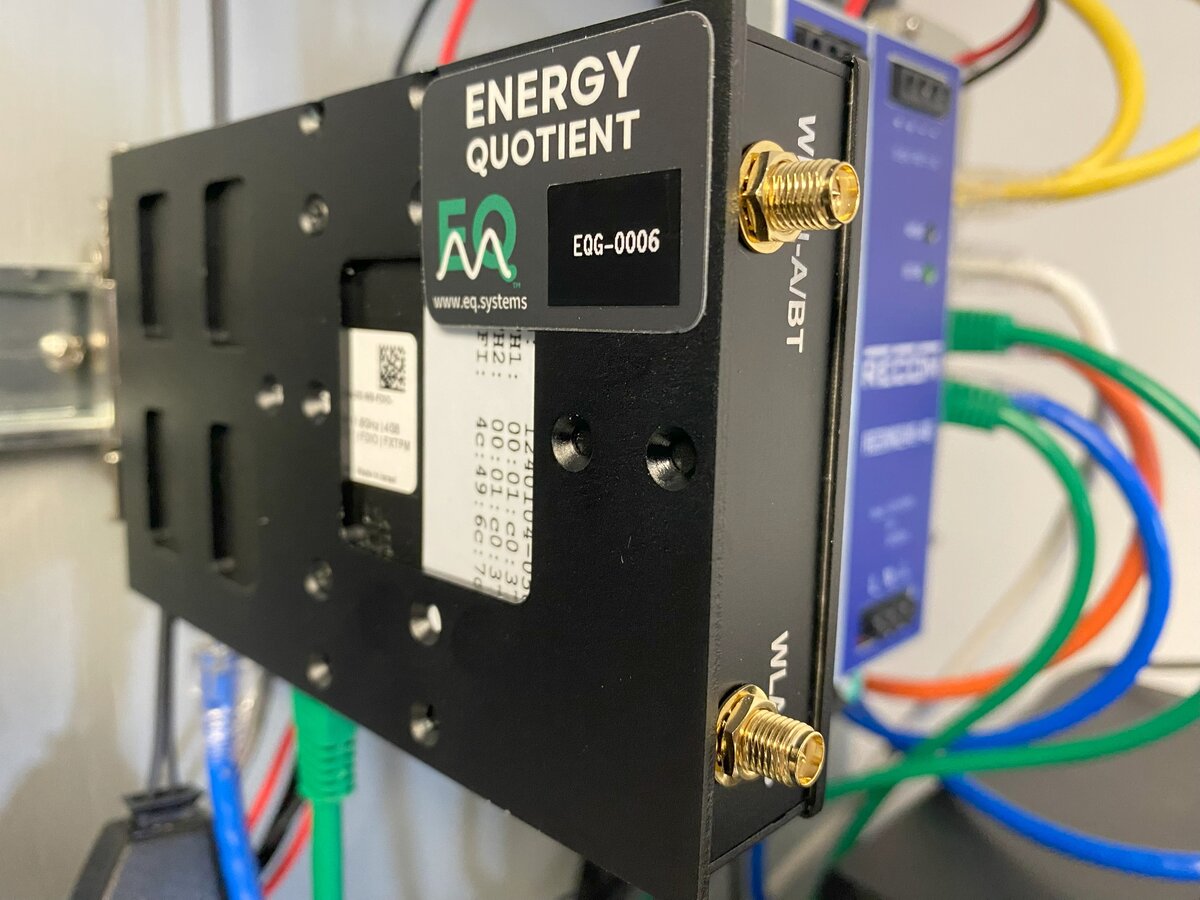
EQ Gateway DIN-rail mounted in instrumentation panel
Models
- IOT-GATE-iMX8PLUS — Panel mount
- IOT-DIN-iMX8PLUS — DIN-rail form factor
Technical Specifications
- Processor: NXP i.MX8M-Plus quad-core ARM Cortex-A53
- Power: 8–36V DC (standard) or PoE 802.3af/at (IOT-GATE only), 5–12W typical
- Operating Temperature: -40°C to +80°C (industrial grade)
- Network: Dual Gigabit Ethernet, 802.11ac dual-band WiFi, optional cellular
- Boot media: eMMC (internal)
- Data storage: microSD via USB adapter (see Storage Media)
Included Storage
- SanDisk Ultra 1.5 TB microSDXC UHS-I Memory Card — approximately one month of retention for a typical 3-phase deployment
- SanDisk MobileMate USB 3.0 microSD Reader (SDDR-B531-AN6NN)
Power Supply Options
Gateway power options (use one):
- PoE 802.3af/at via the LAN port (IOT-GATE panel-mount model only; not available on IOT-DIN)
- Wall power adapter to DC (Compulab IOTG-ACC-PSU)
- Existing DC supply (8–36V, 36W)
The left diagram below shows all possible power paths for each device. It is a reference — do not use all paths simultaneously. The right diagram shows a recommended configuration using PoE for the gateway with USB passthrough to the media converter.

All power options by device (use one per device)

Recommended: PoE gateway + USB-powered media converter
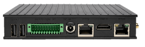
Ethernet Ports
The Compulab gateway has two Ethernet ports with two different roles:
- Sensor port — Connects to the EQ Wave sensor via the media converter. Fixed at 192.168.10.2/24.
- LAN port — Connects to your facility network. Configurable via LAN Configuration. PoE power input, if used, connects here.
warning
IOT-GATE: The case label ETH2 corresponds to OS interface eth0 (the LAN port). If you see eth0 in the OS, that is the LAN port, not the sensor port.
IOT-DIN: Case labels match OS interface names (ETH1 → eth1, ETH0 → eth0).
| IOT-GATE Case Label | IOT-DIN Case Label | OS Interface | Role | |
|---|---|---|---|---|
| Sensor port | ETH1 | ETH1 (top) | eth1 | EQ Wave connection |
| LAN port | ETH2 | ETH0 (bottom) | eth0 | Facility network (PoE on IOT-GATE) |
For other gateway hardware (Raspberry Pi, flex deployments), port assignments differ. See Port Assignments for the complete table.
LED Status Indicators
The gateway uses two bi-color (green/red) LEDs to show service status:
- Power Monitor (pmon) Service:
- Green: Blinks at ~2.5Hz (every 10/12 cycles) during normal operation
- Red: Lights up to indicate error conditions
- Waveform (wave) Service — typically the 2nd LED:
- Green: Blinks at ~2.5Hz during normal operation
- Red: Lights up to indicate error conditions
The gateway’s RJ45 Ethernet ports have amber LEDs for link and green LEDs for activity.
The gateway also has a green LED on the power button, to indicate the device is powered up.
For EQ Wave sensor and media converter LED indicators, see EQ Wave Installation.